General Principles of Pumping Station Design and Layout - 09...
Chapter - 09 : Appendix A - Plates...
Plate 1...
Section views of the gatewell type pumping station illustrating the different type discharge systems.
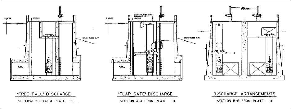 Plate 2...
A pumping station with the pump(s) located in a gatewell. The pumps used at this station were submersible propeller type
supported in a discharge tube fitted with flap gates. This type station is economical to construct. This station is the
Pelucia Creek Pumping Station located in Greenwood, Mississippi. It was designed by the St. Louis District and constructed
by the Vicksburg District and is part of the Yazoo River Basin, Greenwood Protection Works Project.
 Plate 3...
Plan views of the gatewell type station shown in Plate 2. The pump discharge tube location was determined by model tests at
WES. The discharge tube is placed out of the flow area of the gravity drain. Two different discharge methods are shown to
illustrate types of discharge when using a submersible pump.
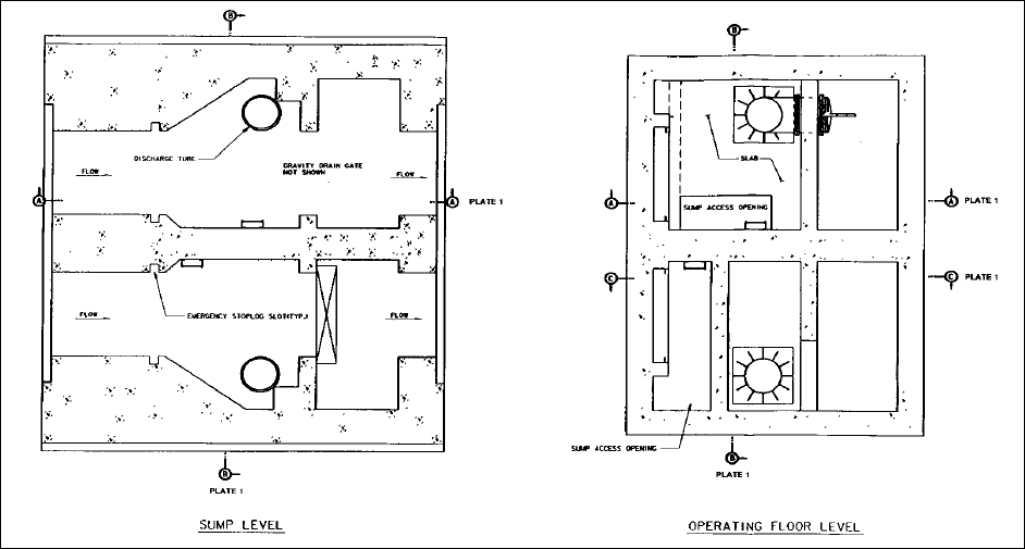 Plate 4...
Section view of a 7-cu-m/sec (250-cfs) pump at Lake Chicot Pumping Plant. This view shows the vertical pump, siphon
discharge, and electric motor drive. This station is located in the Mississippi levee system. It is a project of the
Vicksburg District.
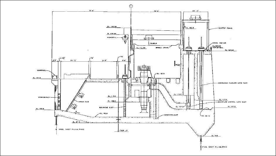 Plate 5...
Site plan for the Lake Chicot Pumping Plant shown in Plate 4.
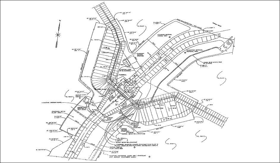 Plate 6...
This pumping station contains five submersible pumps each discharging into a discharge chamber. Flow is taken from a
stormwater sewer. An intake is used to provide correct flow to the pumps. This intake diffuser was model tested by the
pump manufacturer. This pumping station, the Northside Pumping Station located in Richmond, Virginia, was designed by the
St. Louis District and constructed by the Norfolk District as part of the James River Basin, Richmond Local Flood
Protection Project.
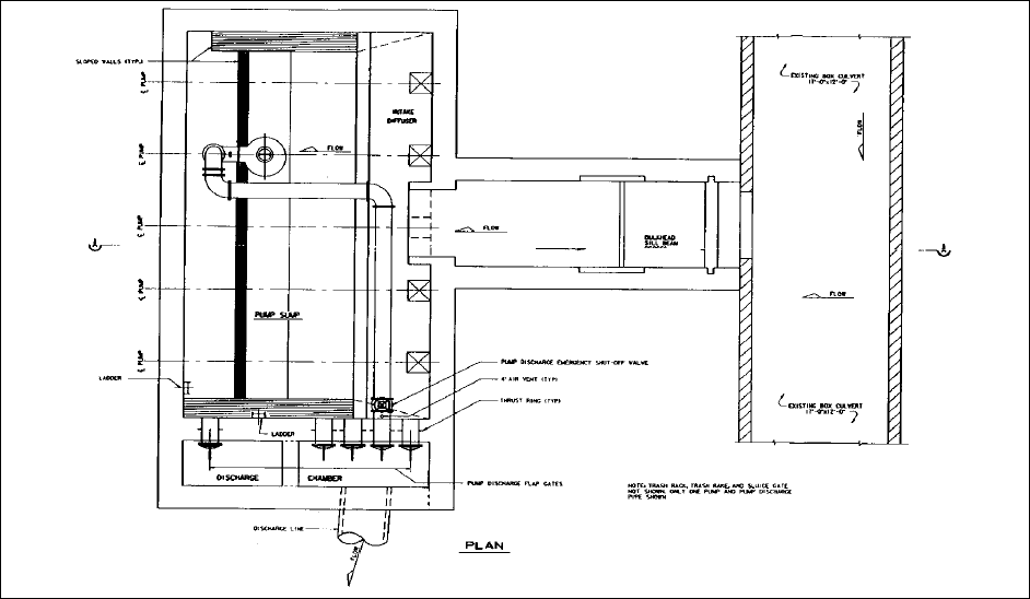 Plate 7...
A section through the sump and forebay of the pumping station shown in Plate 6. The station is provided with a sump intake
gate and mechanical trash raking equipment. A full operating room with an overhead crane and roof ventilator was provided.
The site for this station required a full building over the sump rather than a partial building housing electrical equipment
and office space.
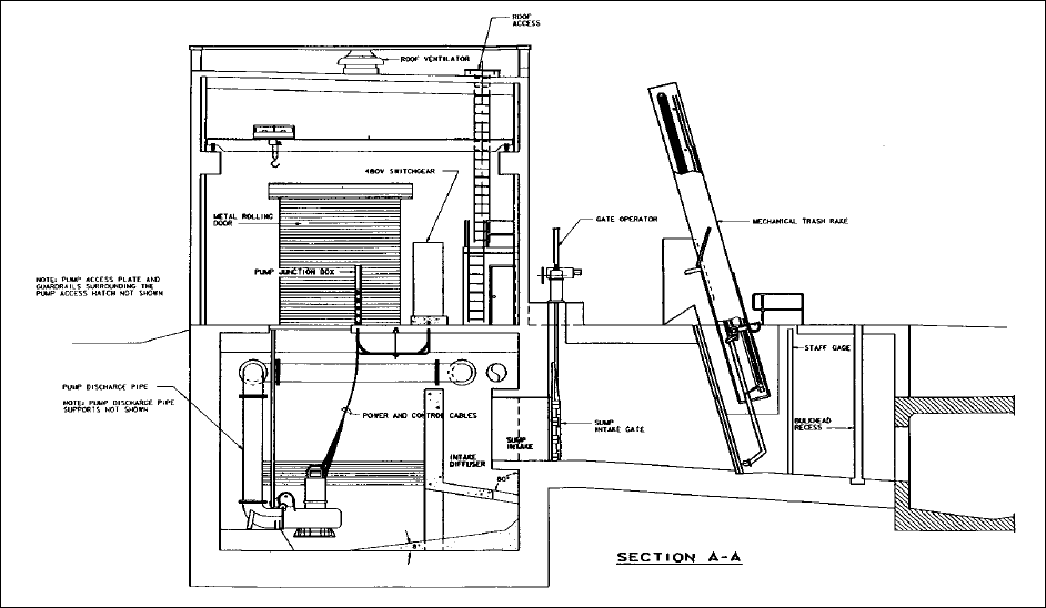 Plate 8...
A pumping station equipped with a discharge chamber, formed suction intake (FSI) on the pump, mechanical trash rake, and
sump closure gate. The station has an electric-motor-driven overhead hoist and uses station layout including gravity drains
under the discharge chambers in the discharge chamber. Bulkhead slots for stopping back flow are not shown. This station is
the Alton Pumping Station and is located in Alton, Illinois. It was designed and constructed by the St. Louis District as
part of the Melvin Price Locks and Dam Project.
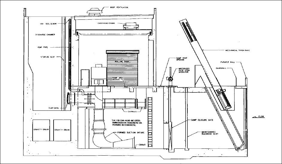 Plate 9...
A site plan for the pumping station shown in Plate 8. The station is located landside of the line of protection (levee).
Note the emergency closure structure located on the pressure conduits riverside of the line of protection. A structure of
this type is required when the discharge chamber of a pumping station is located landside of the line of protection.
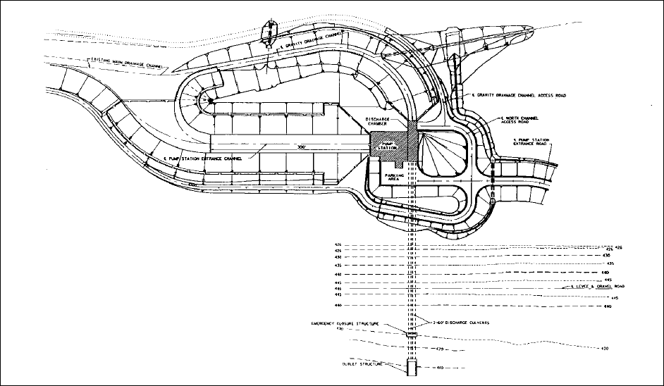 Plate 10...
A pumping station with an over-the-levee discharge system. The station is also equipped with a siphon assist discharge. The
discharge pipe terminates with a saxophone discharge. This station is the Chauvin Bayou Pump Station and is located in
Monroe, Louisiana. It was designed by the St. Louis District and constructed by the Vicksburg District as part of the
Ouachita River Basin, Monroe, Louisiana, Flood Protection Project.
 Plate 11...
A site plan for the pumping station shown in Plate 10. The station is located adjacent to the gravity flow structures. A
separate inlet structure had to be provided to the pumping station.
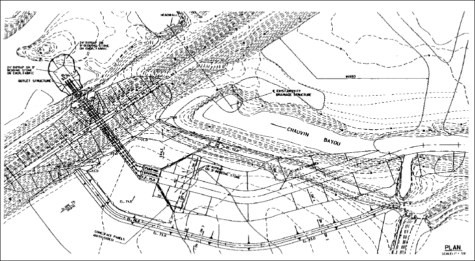 Plate 12...
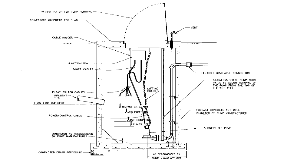
This pumping station design is used when required pumping capacity is less than 566 L/sec (20 cfs). The pumps are
submersible type and are removed by the use of guide rails and a discharge connection fastened to the floor. The size of
the inlet lines to the station are usually small and limit the trash size that reaches the pump. A removable trash basket
can be used to catch large objects. This type station may be located where occasional flooding is possible without any
damage to the equipment.
