Mechanical and Electrical Design of Pumping Stations - 15...
Chapter - 15 : Power Distribution Equipment...
15-1. General...
The power distribution equipment for motors used in
flood-protection pumping stations must be as simple as
possible, compact, and reliable, and since the equipment
will stand idle for long periods and be subject to wide
temperature variations, provisions must be made to prevent
condensation within control enclosures
(Plates 12-19). See Chapter 20, "Electrical Equipment
Environmental Protection," for recommended protective
requirements.
15-2. Main Disconnection Device...
( a ) General.
The main pumping station disconnecting
device should be located within the station as part of the
motor control center (for low-voltage stations) or the
motor controller line-up (for medium-voltage stations).
The main for the motor control center could be a molded
case circuit breaker, power air or vacuum circuit breaker,
or a quick-make, quick-break fusible interrupter switch.
Similarly, the medium-voltage motor controller line-ups
can utilize high-voltage load interrupter switches or
power circuit breakers of the air or vacuum type.
( b ) Design decision.
The design decision between a
fusible interrupter switch and a circuit breaker ultimately
depends upon the specific application. In some cases,
continuous current requirements or interrupting capacities
will dictate. Below 600 volts, circuit breakers and fuses
are generally available in all continuous current ratings
and interrupter ratings likely to be encountered. At the
medium-voltage level, however, fuses are usually limited
to 720 amperes continuous with 270 mVA maximum
interrupting capacity. Additionally, at this continuous
current level, the slow interrupting characteristics of the
fuse often presents coordination problems with the utility’s
overcurrent protective relaying. A new product,
current limiting electronic fuses, improves the fuse reaction
time by electronic sensing of the rate of change of
current. It should be considered when coordination is a
problem. In any event, the utility should be advised of
the choice of main disconnect in order to ensure compliance
with their standards and to prevent coordination
problems. If a fusible interrupter switch is selected,
protection from single phasing should also be provided.
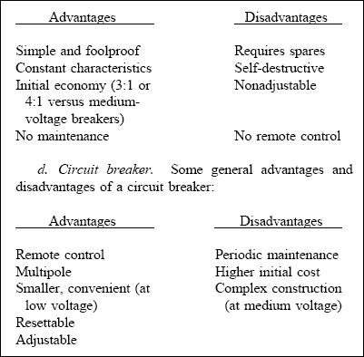
( c ) Fusible interrupter switch.
Some general advantages and disadvantages of a fusible interrupter switch include:
 15-3. Low-Voltage Stations...
( a ) General.
15-3. Low-Voltage Stations...
( a ) General.
In general, motor control centers are
preferred over "metal enclosed low-voltage power circuit
breaker switchgear" for control of motors 480 volts and
below in pumping station design. While metal-enclosed
switchgear is a high quality product, its application is
found more in feeder protection and starting and stopping
of infrequently cycled motors and generators.
( b ) Maintenance.
Experience has shown that frequent
operation of power circuit breakers requires additional
maintenance of the various mechanical linkages that
comprise the operating mechanisms. Since maintenance
of pumping station equipment is usually a local levee or
sewer district responsibility, every effort should be made
to reduce system maintenance and optimize station reliability.
Magnetic starters provide a simple, reliable, and
less expensive alternative to the usage of power circuit
breakers. Combination magnetic starters are available in
either the circuit breaker or fusible type.
( c ) Motor protection.
Protection of the motor is provided
by thermal overload relays, which are normally
built into the starter itself. The relays contain high-wattage electric heaters, in each phase, which are
heated by the passage of motor current. The heat generated
either bends a bi-metallic strip or melts a low temperature
(eutectic) fusible alloy. The bent bi-metallic
strip opens contacts that interrupt the current to the contactor-
operating coil. The melted alloy frees a springloaded
shaft that rotates and breaks contacts in the
operating coil circuit. The bi-metallic relay has two
advantages not found in the fusible-alloy type: it can
reset itself automatically and can compensate for varying
ambient-temperature conditions if the motor is located in
a constant temperature and the starter is not. The heaters
must be sized to accept the starting current of the motor
for the expected starting time without causing the contactor
to open. To achieve this with a variety of connected
loads, conventional starters are available with a
range of standard heaters, which can be selected according
to the application.
( d ) Undervoltage protection.
Undervoltage protection
is supplied inherently by the action of the operating coil.
An abnormally low supply voltage causes the motor to
run well below synchronous speed, drawing a current
which, even though not as high as the starting current,
quickly overheats the motor. A low supply voltage,
however, also means a low current to the holding coil
and causes the contactor to drop out and isolate the
motor. If more protection from undervoltage is required,
an undervoltage relay can be added for increased
protection.
( e ) Combination motor controllers.
Combination
duplex or triplex motor controllers are sometimes provided
by the pump manufacturer as part of a pump,
motor, controller package. This is often the case for
smaller stations employing submersible motors. This is a
viable option, where applicable, and assures one manufacturer
responsibility should problems arise.
15-4. Medium-Voltage Stations...
( a ) General.
The designer must choose between a
medium-voltage motor controller (incorporating a magnetic
contactor) and an air-magnetic or vacuum circuit
breaker. While "metal-clad" switchgear is the highest
quality equipment produced by the industry, motor controllers
are still preferred. Circuit breakers in metal-clad
switchgear are used as motor starters primarily by utilities,
where a motor, once started, may run a week or
more without stopping. In industry, circuit breakers find
their application as main or feeder breakers that are not
frequently opened or closed.
(1) Circuit breaker benefits. The benefit of circuit
breakers is that although the contact mechanism is not
designed for a large number of operations, it is designed
to interrupt short-circuit currents of high magnitude and
be returned to service immediately. While vacuum bottle
technology increases the number of operations possible,
contactors are still the preferred mechanism for frequently
started motors.
(2) Cost. Another consideration in the choice
between the two is the relative cost. Metal-clad
switchgear is approximately three times as expensive as
an equivalent line-up of motor controllers. Where
required, air or vacuum circuit breakers can be used as
mains with transition sections to accommodate the motor
controller line-up.
( b ) Medium-voltage motor controllers.
The mediumvoltage
controllers should comply with NEMA ICS
2-324, "A-C General-Purpose High-Voltage Class E
Controllers" and UL Standard 347 (Underwriters Laboratories,
Inc. 1985). They may be described as
metal-enclosed high-interrupting capacity, drawout, magnetic-
contactor type starter equipments with manual
isolation. Medium-voltage motor controllers are available
for reduced-voltage and full-voltage starting of nonreversing
squirrel-cage and full-voltage starting of
synchronous motors typically used in pumping stations.
(1) High- and low-voltage sections. Each motor
controller enclosure is divided into a high- and lowvoltage
section. The high-voltage section contains the
magnetic contactor and its protective fuses. The lowvoltage
section contains the controls and protective
relaying. Contingent upon motor size and relaying
requirements, one, two, or three starters can be located in
one vertical section. Power for control relays is usually
115 volts but may be 230-volt AC or 48-, 125-, or
250-volt DC.
(2) Fuses. The contactor itself is not capable of
interrupting a short circuit and must be protected by
silver-sand type current limiting fuses. Fuses are generally
mounted on the contactor itself and can be drawn out
of the cabinet for replacement by withdrawing the contactor.
One limitation of such fuses is that, should a
short-circuit occur on one phase only, only that fuse will
blow, and the motor will continue to operate on the
single phase between the remaining two lines. Current
drawn in that phase is twice full-load current and will
rapidly overheat the motor. This can be avoided by the
addition of suitable relaying, as described later, but, in some cases, the contactor may also incorporate a trip
mechanism that is actuated by the blown fuse itself. The
trip mechanism causes the contactor to open immediately
when the fuse is blown, isolating the motor. Either protective
relaying or a mechanical trip mechanism should
be provided.
( c ) Motor protection.
(1) General. The following gives general guidance
for protection of medium-voltage motors. For further
information on motor protection, refer to ANSI/IEEE
242, "Recommended Practices for Protection and Coordination
of Industrial and Commercial Power Systems."
For motor protection against lightning and switching
surges, refer to Chapter 19.
(2) Induction motor protection. It is logical that
more extensive protection be considered for larger motors
than for smaller motors, since they represent a larger
capital investment. Therefore, minimum recommended
protective relaying is divided into two groups: one for
motors rated below 375 kW (500 HP), and the other for
those rated 375 kW (500 HP) and above.
(a) Motors below 375 kW (500 HP). Referring to
Figure 15-1, for motors rated below 375 kW (500 HP),
protection against loss of voltage or low voltage is generally
provided by the single-phase time-delay undervoltage
relay, Device 27. Where it is desired to secure threephase
undervoltage protection, such as when the motor is
fed through fuses or from an overhead open line wire,
Device 47 would be used in place of Device 27. In
addition, Device 47 would provide protection against
phase sequence reversal should it occur between the
source and the motor’s associated switchgear. The
Device 49/50 provides short-circuit, stalled-rotor, and
running overload protection; this relay has a thermally
operated time-overcurrent characteristic. It is therefore
generally to be preferred for this application over an
inverse time-overcurrent relay such as the Device 51
relay. The instantaneous device on the Device 49/50
relay is normally set at 1.6 to 2 times locked-rotor
current. Sensitive and fast ground-fault protection is
provided by the instantaneous ground-sensor equipment,
Device 50GS. Device 49 operates from a resistancetemperature
detector embedded in the machine stator
winding. This type of running overload protection is to
be preferred over the stator-current-operated device, since
it responds to actual motor temperature. The Device 40S
provides protection against stalled rotor conditions. This
device is necessary since the resistance-temperature
detector used with Device 49 will not respond immediately to fast changes in the stator conductor temperature
as would be the case under stalled conditions.
The Device 49S relay includes a special high-drop-out
instantaneous-overcurrent unit which is arranged to prevent
its time-overcurrent unit from tripping except when
the magnitude of stator current is approximately equal to
that occurring during stalled conditions. Device 48, the
incomplete sequence timer, would be included where the
control package is of the reduced-voltage type. It provides
protection for the motor and control package
against continued operation at reduced voltage which
could result from a control sequence failure. For woundrotor
motors where the starting inrush current is limited,
more sensitive short-circuit protection can be provided
with the addition of the Device 51 time over-current
relays. With the motor inrush current limited, these
relays can generally be set to operate at full-voltage
locked-rotor current with all secondary resistance shorted.
(b) Motors rated 375 kW (500 HP) or above. For
the larger motors rated 375 kW (500 HP) and above, a
current-balance relay, Device 46, is included to provide
protection against single-phase operation. Differential
protection for larger motors is provided by Device 87.
This device provides sensitive and fast protection for
phase-to-phase and phase-to-ground faults.
(3) Medium-voltage brushless synchronous motor
protection. Figure 15-2 covers the recommended minimum
protection for brushless synchronous motors.
Device 26 has been included to provide stalled-rotor
protection. It is a stator-current operated device. The
characteristic and rating of this device is provided by the
equipment manufacturer and must be closely coordinated
with the starting and operating characteristics of the
individual motor being protected. The power factor relay
Device 55 has also been included to protect the motor
from operating at sub-synchronous speed with its field
applied. This commonly called out-of-step operation will
produce oscillations in the motor stator current, causing
them to pass through the "lagging" quadrature. The
power factor relay is connected to sense this current and
will operate when it becomes abnormally lagging. Upon
operation, excitation is immediately removed from the
motor, allowing it to run as an induction machine. After
excitation has been removed, the control is arranged to
shut down the motor.
(4) Microprocessor-based motor protection systems.
Microprocessor-controlled motor protective systems are a
relatively recent development that combines control,
monitoring, and protection functions in one assembly.
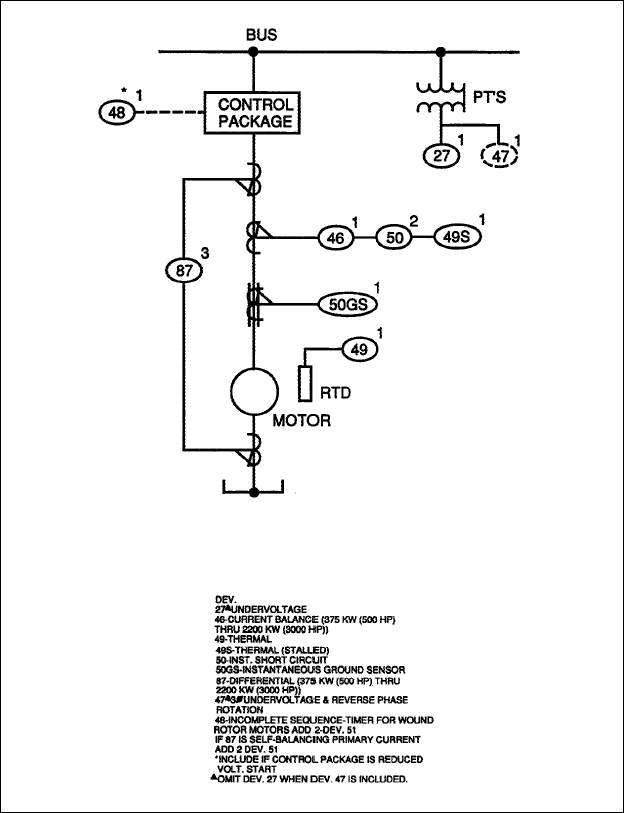
Figure 15-1. Recommended minimum protection for medium-voltage induction motors (all horsepowers except as noted).
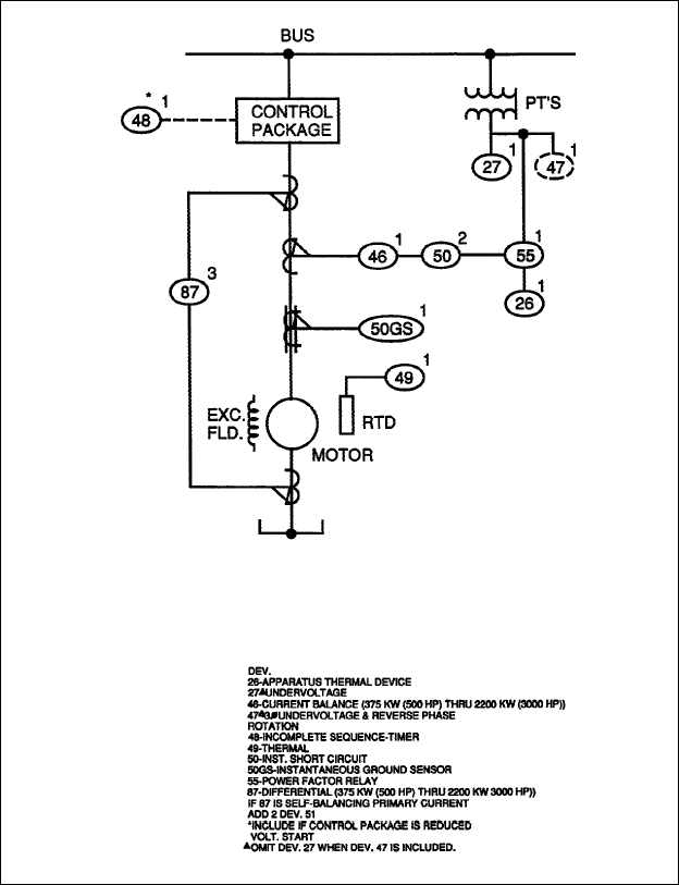
Figure 15-2. Recommended minimum protection for medium-voltage brushless synchronous motors (all horsepowers except as
noted).
Most protection packages provide complete motor protection
for any size motor. The packages usually include
motor overload protection, overtemperature, instantaneous
overcurrent, ground fault, phase loss/phase reversal/phase
unbalance (voltage), phase loss and unbalance (current),
overvoltage, undervoltage, and motor bearing temperature
protection. The monitoring features include current,
voltage, watts, frequency, power factor, and elapsed time.
Some units can tabulate the number of starts per programmed
unit of time and lock out the starting sequence,
preventing inadvertent excessive cycling. The control
features replace discrete relay logic for prestart, poststart,
prestop, and poststop timing functions and various
enabling signals. Programmable logic under the control
of the processor performs these functions. The units can
be programmed for simple, across-the-line starting or
more complex starting sequences such as reduced-voltage
autotransformer starting. Also included are adjustable
alarm and trip parameters and self-diagnostics including
contractor report-back status to enhance system reliability.
In instances where motor conditions exceed the
programmed setpoint values, an alarm and/or trip condition
is automatically initiated. One of the advantages to
these systems is that there are few options making it less
likely that a desired protective feature will be overlooked
in the specification process.
(5) Considerations. Microprocessor-controlled protection
packages are a viable option when precise and
thorough motor protection is required. After the designer
has decided upon the minimum required protective features,
as described above, an economic comparison
should be made between standard methods of relay protection
versus the microprocessor-based systems. Consideration
should be given to the microprocessor system’s
added features such as the built-in logic capabilities,
expanded motor protection, and monitoring and alarm
functions when making the cost comparison. As with all
solid state devices, careful consideration must be given to
their operating environment. The typical operating range
of the processor is -20 to 70 degrees centigrade. However,
the operating temperature of the external face of the
operator panel is limited to 0 to 55 degrees centigrade.
Special coating of the circuit boards is, also, required to
provide protection from the extremely humid environment
of the typical pumping station. The applications
department of the manufacturer should be consulted for
each application.